Ultimate Anti-Buddhagram
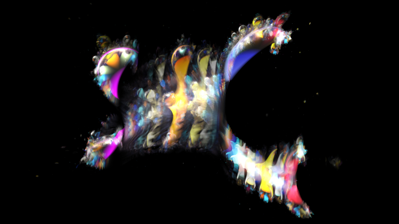
Melinda Green's webpage The 4D Mandel/Juli/Buddhabrot Hologram has a nice video at the bottom, titled ZrZi to ZrCr - only points Inside the m-set. I recalled my 2013 blog post about the Ultimate Anti-Buddhabrot where I used Newton's method to find the limit Z cycle of each C value inside the Mandelbrot set and plotted them. The (anti-)Buddhagram is just like the (anti-)Buddhabrot, but the Z points are plotted in 4D space augmented with their C values. Then the 4D object can be rotated in various ways before projection down to 2D screen, possibly via a 3D step.
My first attempt was based on my ultimate anti-Buddhabrot code, computing all the points in a fine grid over the C plane. I collected all the points in a large array, then transformed (4D rotation, perspective projection to 3D, perspective projection to 2D) them to 2D and accumulated with additive blending to give an image. This worked well for videos at moderate image resolutions, achieving around 6 frames per second (after porting the point cloud rasterization to OpenGL) at the highest grid density I could fit into RAM, but at larger sizes the grid of dots became visible in areas where the z→z²+c transformation magnified it.
Then I had a flash of inspiration while trying to find the surface normals for lighting. Looking at the formulas on Wikipedia I realized that each "pringle" is an implicit surface \(F_p(c, z) = 0\), with \(F_p(c, z) = f_c^p(z) - z\) and the usual \(f_c(z) = z^2 + c\). \(p\) is the period of the hyperbolic component. Rendering implicit surfaces can be done via sphere-marching through signed distance fields, so I tried to construct a distance estimate. I tried using \(|F_p(c, z)| - t\) as a first try, where \(t\) is a small thickness to make the shapes solid, but that extended beyond the edges of each pringle and looked very wrong. The interior of the pringle has \(\left|\frac{\partial F_p}{\partial z}\right| \le 1\) so I added that to the distance estimate (using max() for intersection) to give:
float DE(vec2 c, vec2 z0)
{
  vec2 z = z0;
  vec2 dz = vec2(1.0, 0.0);
  float de = 1.0 / 0.0;
  for (int p = 1; p <= MaxPeriod; ++p)
  {
    dz = 2.0 * cMul(dz, z);
    z = cSqr(z) + c;
    de = min(de, max(length(z - z0), length(dz) - 1.0));
  }
  return 0.25 * de - Thickness;
}
Note that this has complexity linear in MaxPeriod, my first attempt was quadratic which was way too slow for comfort when MaxPeriod got bigger than about 10. The 0.25 at the end is empirically chosen to avoid graphical glitches.
I have not yet implemented a 4D raytracer in FragM, though it's on my todo list. It's quite straightforward, most of the maths is the same as the 3D case when expressed in vectors, but the cross-product has 3 inputs instead of 2. Check S. R. Hollasch's 1991 masters thesis Four-Space Visualization of 4D Objects for details. Instead I rendered 3D slices (with 4th dimension constant) with 3D lighting, animating the slice coordinate over time, and eventually accumulating all the 3D slices into one image to create a holographic feel similar to Melinda Green's original concept.
Source code is in my fractal-bits repository:
git clone https://code.mathr.co.uk/fractal-bits.git
